A marine cable must operate where moisture, salt, vibration, chemicals, mechanical loading, and restricted installation space may occur together. Selecting only by conductor size or voltage can therefore leave important environmental and safety risks unresolved. Buyers also need to distinguish shipboard wiring from cables installed on offshore structures or permanently submerged beneath the sea. The following sections classify marine electrical cables by function, explain the protective constructions available, and show how to match each marine cable to automation, energy, oil and gas, and offshore wind applications.
Classify Marine Cable Types by the Job They Perform
Marine cable terminology can become confusing because some names describe the circuit function, while others describe a material or protective feature. Power, control, instrumentation, and communication are functional categories. Armored, flexible, waterproof, oil-resistant, flame-retardant, and low-smoke constructions are performance options that may be applied to several functional categories. A practical specification should first identify what the cable must carry and then define the protection required for its installation zone.
Power Distribution and Submarine Power Cables
Marine power cables distribute electrical energy from generators, transformers, or switchboards to motors, lighting, pumps, deck machinery, and auxiliary systems. Low-voltage cables commonly serve local distribution, while medium-voltage systems may be used where equipment ratings or transmission distances make higher voltage more practical. Conductor area must be selected for load current, voltage drop, short-circuit duty, installation method, grouping, and ambient temperature rather than load current alone.
Submarine power cables form a separate group because they are designed for continuous underwater service and installation loads. The High Voltage Submarine Cable range includes copper or aluminum conductors, single- or three-core configurations, XLPE insulation, water-blocking layers, and metallic armor. Listed applications include offshore wind connections, coastal and island interconnections, subsea renewable-energy networks, and offshore platform power supply.
Control and Instrumentation Cables
Control cables carry commands, status signals, and interlocking functions between control panels, actuators, relays, valves, and machinery. Instrumentation cables serve sensitive measurement circuits associated with pressure, temperature, flow, level, and other process variables. Although their functions overlap, instrumentation circuits often require tighter control of electromagnetic interference and pair-to-pair crosstalk.
A screened or braided design can protect low-level signals when the route passes near motors, variable-frequency drives, power feeders, or switching equipment. The Flexible Control Cable page describes multi-core, shielded, armored, and low-smoke halogen-free options. It also identifies salt-spray- and moisture-resistant versions for offshore platforms and marine automation systems.
Communication and Fiber Optic Cables
Communication cables support data networks, monitoring systems, alarms, navigation equipment, platform communications, and links between offshore assets. Copper data cables can be suitable for shorter links, but fiber optics provide high data capacity without conducting electrical current and are unaffected by electromagnetic interference. Their performance still depends on suitable mechanical protection, water blocking, termination methods, and routing.
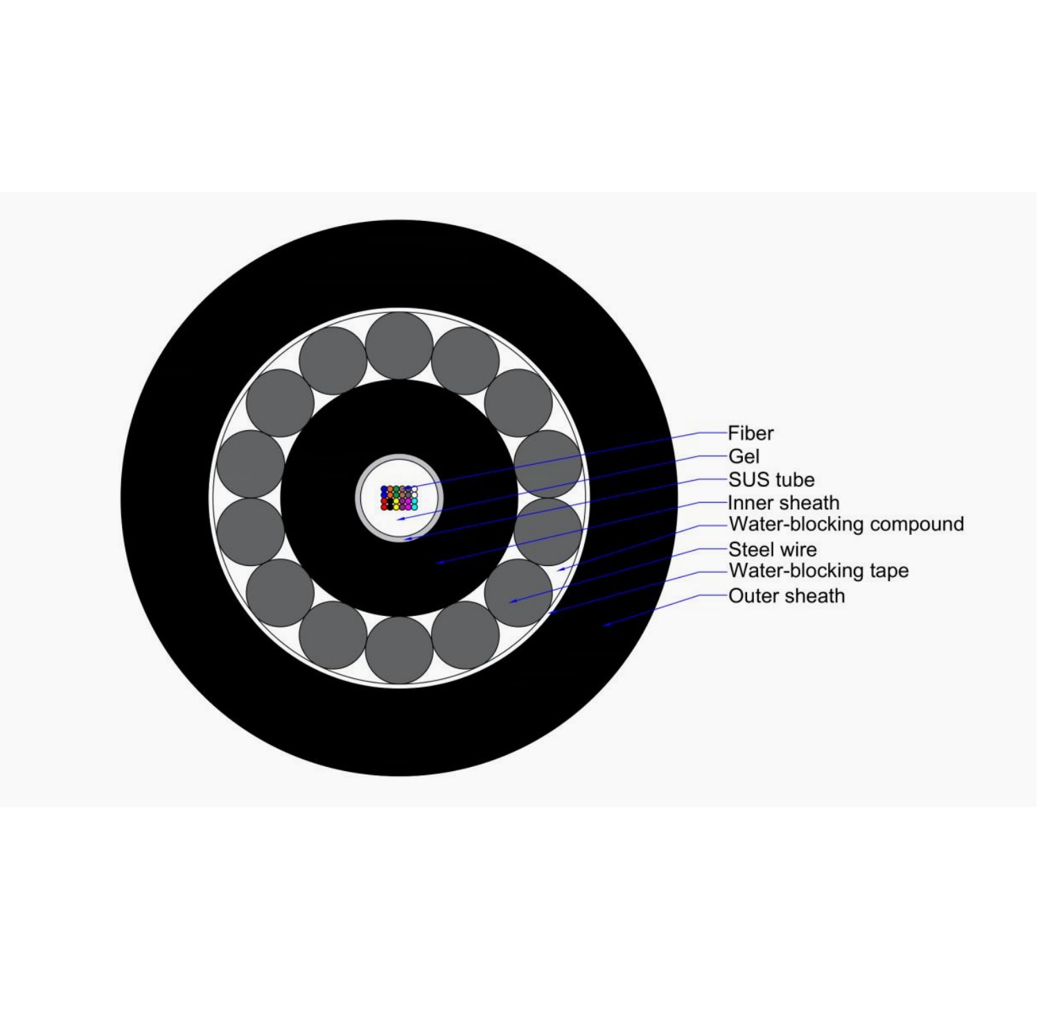
For underwater and long-distance links, an Offshore Fiber Optic Cable can incorporate an optical unit, filling compound, strength member, waterproof barrier, steel-wire armor, and PE outer sheath. Lightweight, single-armored, and double-armored structures can be considered according to installation depth, seabed conditions, tensile loading, and exposure to external damage.
Special-Service Marine Cables
Special-service cable names describe environmental or mechanical performance rather than the connected equipment. Flexible cables are used where movement, vibration, or difficult routing makes a rigid construction unsuitable. Armored designs add resistance to impact, crushing, tension, and other external forces, but the extra layers increase diameter, weight, and bending stiffness.
Fire-resistant and flame-retardant cables also serve different purposes. Flame-retardant construction limits flame spread, while a fire-resistant cable is intended to preserve circuit operation for a defined test period. Emergency lighting, alarms, shutdown systems, and critical communications may therefore require different evidence from ordinary power or control circuits.
Match Marine Cable Construction to the Exposure Zone
A cable installed inside a protected equipment room faces different conditions from one routed across an open deck, through a splash zone, down a turbine tower, or along the seabed. Environmental classification should consider continuous immersion, intermittent spray, condensation, ultraviolet exposure, temperature, chemicals, vibration, abrasion, and potential impact. Calling every wet-area product a marine cable is not enough because occasional moisture resistance does not automatically prove suitability for permanent submersion.
Where moisture ingress is the main risk, a Waterproof Cable uses water-resistant insulation or sealing structures to help protect conductors in wet, outdoor, underground, or marine installations. The required construction still depends on whether exposure involves humidity, direct spray, temporary flooding, or continuous underwater pressure. Joints, glands, and terminations must provide protection consistent with the cable itself; otherwise, water can enter at the connection even when the outer sheath remains intact.
Engine rooms, hydraulic systems, drilling equipment, and processing areas may expose cable jackets to fuel, lubricants, grease, or chemicals. An Oil Resistant Cable uses jacket and insulation materials selected to reduce oil-related swelling, softening, cracking, or loss of mechanical strength. Oil resistance should be assessed together with temperature, abrasion, moisture, and the specific fluid involved because one general resistance label may not cover every chemical concentration or exposure duration.
Mechanical protection must also match the route. Armor may be appropriate for exposed, buried, or subsea sections, while a flexible unarmored construction may perform better in protected routes that experience repeated movement. Shielding is selected for electromagnetic compatibility, not as a substitute for armor or water blocking. Similarly, an LSZH sheath can reduce smoke and halogen emissions during a fire but does not independently establish circuit integrity or permanent underwater suitability.
Match Cable Families to Offshore Applications
Each offshore project normally requires several marine cable families rather than one universal construction. The table below links common application areas to their principal circuits and selection priorities.
Water blocking, tensile loading, seabed risk, data links, dynamic movement
Subsea connections
Armored power or fiber optic cables
Pressure, installation tension, abrasion, water ingress, repair accessibility
Marine automation depends on reliable coordination between sensors, controllers, actuators, drives, and safety systems. Power circuits should be separated from sensitive signal routes where practical, while screens, grounding arrangements, and cable geometry should be selected as part of the complete electromagnetic-compatibility design. Flexibility is especially relevant around moving assemblies, compact cabinets, and routes subject to vibration.
Offshore wind farms combine internal turbine wiring, array connections, export circuits, condition monitoring, and communications. Oil and gas platforms add demanding process environments where oil exposure, fire performance, mechanical protection, and signal integrity may all affect one cable specification. Subsea circuits introduce further risks during manufacturing, load-out, transportation, laying, burial, operation, and possible recovery. Subsea power cable design and assurance should therefore be treated as a lifecycle process rather than a product-only decision.
Use a Structured Marine Cable Selection Process
Begin with the electrical duty. Record system voltage, operating current, permissible voltage drop, short-circuit level, frequency, conductor configuration, and connected equipment. For control and instrumentation circuits, also define signal type, pair or core count, screening arrangement, capacitance limits, and grounding philosophy. A marine cable selected without complete circuit data may be oversized in one respect but inadequate in another.
Next, document the installation route section by section. Identify protected indoor areas, exposed decks, splash zones, machinery spaces, chemical areas, dynamic sections, buried routes, and permanently submerged sections. Record the expected temperature, minimum bending space, vibration, pulling tension, support interval, impact risk, and accessibility for replacement. This route-based method often reveals that different sections require different cable constructions or engineered transitions.
Fire requirements should be specified independently from moisture and mechanical performance. Determine whether the circuit requires flame propagation control, reduced smoke and corrosive gas emissions, or continued operation during fire. Emergency and safety circuits may require stricter construction, routing, separation, and testing than ordinary services. The certificate, test report, and applicable standard should correspond to the actual cable design offered, rather than a broad product category.
The IEC 60092 series provides separate requirements for cable construction, power circuits, control and instrumentation circuits, and cable selection and installation aboard ships and offshore units. IEC 60092-350 addresses general construction and testing, IEC 60092-353 covers specified shipboard and offshore power cables, and IEC 60092-376 applies to screened and unscreened control and instrumentation cables. IEC 60092-352 addresses selection, installation, and operating conditions, including fixed systems affected by ship vibration or motion.
Standards alone do not complete the specification. The purchaser should confirm the project edition, classification requirements, authority approvals, installation rules, and documentation expected for the vessel or offshore unit. Submarine and dynamic offshore cables may also require project-specific analysis beyond ordinary shipboard cable standards. Final review should compare the datasheet, construction drawing, test plan, accessories, jointing system, and route assumptions as one package.
Avoid Installation and Maintenance Failures
Even a correctly selected marine cable can fail prematurely when pulling tension, sidewall pressure, or minimum bend radius is exceeded during installation. Unsupported spans and overtightened cleats can create concentrated stress, while incompatible glands may damage the sheath or leave an ineffective environmental seal. Subsea systems require controlled handling because installation loads can differ substantially from normal operating loads.
Termination quality deserves equal attention. Armor bonding, screen grounding, conductor preparation, sealing, and strain relief must follow the approved design. Mixing power and sensitive instrumentation in unsuitable routes can introduce interference that appears to be an equipment fault rather than a cabling problem. Commissioning should therefore include relevant insulation, continuity, conductor, screen, optical, and functional tests.
Inspection intervals should reflect environmental severity and circuit criticality. Maintenance teams should look for jacket cracking, flattening, abrasion, loose supports, corrosion, oil-related deterioration, overheated connections, and water entry near glands or joints. Trend records help distinguish isolated damage from repeated problems caused by routing, movement, contamination, or incorrect protection. Repairs should restore the original electrical, mechanical, fire, and environmental performance instead of merely covering visible damage.
Conclusion
Marine cable selection should begin with circuit function and then account for voltage, water exposure, chemicals, movement, mechanical loading, fire behavior, signal interference, and applicable approval requirements. Shipboard, platform, and subsea circuits should not be treated as identical installations. Yongchuang operates as a cable manufacturer and supplier offering power, control, specialty, and communication cable categories. Its verified product range can support more precise matching of cable construction to marine automation, offshore energy, oil and gas platform, and offshore wind requirements.
FAQ
Q: What is the difference between a marine cable and a submarine cable?
A: A marine cable is generally used on ships or offshore units, while a submarine cable is engineered for continuous underwater installation, pressure, water blocking, and seabed loads.
Q: Which marine cable types are used in offshore wind farms?
A: Offshore wind projects commonly use submarine power cables, internal power cables, control and instrumentation cables, and fiber optic cables for grid connection, automation, and monitoring.
Q: Why are marine control cables often shielded?
A: Shielding reduces electromagnetic interference from nearby power cables, motors, and switching equipment, helping sensitive control and instrumentation signals remain stable and accurate.
Q: Is every waterproof cable suitable for permanent submersion?
A: No. Resistance to moisture or temporary water exposure does not automatically establish suitability for continuous immersion, underwater pressure, installation tension, or seabed abrasion.
Q: When is an armored marine cable necessary?
A: Armor is considered where the route exposes cables to impact, crushing, pulling forces, burial hazards, or seabed activity, but it may be unnecessary in protected flexible routes.