A marine cable must carry power, control commands, or communication data while exposed to conditions that can quickly damage ordinary wiring. Moisture, salt, vibration, oil, mechanical loading, restricted routing space, and fire-safety requirements all influence cable construction and installation. Choosing by conductor size or voltage alone can therefore create reliability problems that only appear after commissioning. This introduction explains how marine cable types differ, how protective layers work, and how engineers can match cable performance to marine automation, offshore energy, oil and gas platforms, and offshore wind farms.
Why Marine Conditions Change Cable Requirements
A marine cable operates within an interconnected environment rather than under one isolated hazard. Saltwater and humid air can attack exposed metals, while condensation may enter poorly sealed glands or damaged sheaths. Continuous vibration can loosen supports, stress terminations, and accelerate fatigue near equipment connections. Oil, drilling fluids, cleaning chemicals, ultraviolet exposure, temperature changes, and mechanical impact can further affect the cable jacket, insulation, and service life. Marine cable standards consequently address electrical, mechanical, environmental, material, installation, and operating conditions together rather than treating them as separate purchasing options.
Water resistance must also be matched to the actual exposure. A cable installed in a protected accommodation space faces different risks from one routed across an open deck, through a splash zone, or beneath the seabed. A Waterproof Cable uses water-resistant insulation, sheathing, or sealing structures to reduce moisture ingress in wet, outdoor, underground, and marine installations. However, a waterproof designation does not automatically confirm suitability for permanent submersion, high hydrostatic pressure, dynamic movement, or a specific water depth. Those conditions must appear in the project specification.
Corrosion risk extends beyond direct seawater contact. Salt deposits can remain on exposed equipment, while chemical vapors and moisture can degrade unsuitable polymers or unprotected metallic components. A Corrosion Resistant Cable is intended for humid, salty, chemically aggressive, or industrial environments through protective coatings, insulation, and sheath materials. Engineers should still check compatibility with the exact chemical, expected concentration, exposure duration, and operating temperature. General corrosion resistance is useful, but application-specific compatibility determines whether the cable remains dependable over time.
Fire behavior is equally important because ships and offshore facilities contain enclosed routes where smoke and corrosive gases can obstruct evacuation or damage equipment. Flame propagation, smoke density, and gases released during combustion are separate performance characteristics, so one test result does not prove every fire-safety property. International standards provide distinct procedures for evaluating flame spread, smoke generation, halogen content, and gas corrosivity. The required combination depends on the vessel, offshore unit, installation area, circuit function, and applicable classification rules.
Match the Cable to the Electrical Function
The term marine cable covers several product families with different electrical and mechanical purposes. Selecting the correct family begins with the circuit function, followed by voltage, current, signal characteristics, installation environment, and regulatory requirements. Using a power cable for a sensitive signal circuit may create electromagnetic interference, while using a fixed cable in a continuously moving connection can cause premature mechanical failure. Fixed shipboard systems and applications involving frequent or continual flexing therefore require different cable constructions.
System Function
Typical Marine Cable Role
Main Selection Concern
Power distribution
Supplies generators, switchboards, motors, transformers, and large loads
Voltage rating, ampacity, short-circuit duty, temperature, and mechanical protection
Control and automation
Carries commands, status signals, and measurement data
Core count, shielding, signal integrity, flexibility, and termination layout
Communication
Transfers network, voice, video, and operational data
Bandwidth, attenuation, shielding or fiber design, and route redundancy
Emergency and safety systems
Supports alarms, emergency lighting, shutdown, and fire systems
Circuit integrity, flame performance, smoke behavior, and route protection
Subsea transmission
Connects offshore facilities, wind farms, islands, and coastal grids
Water blocking, armor, tensile load, seabed conditions, and installation method
Marine automation depends on stable signals from sensors, actuators, programmable controllers, monitoring equipment, and safety systems. An Electrical Control Cable can use copper conductors with PVC or XLPE insulation, while optional braid or foil shielding helps reduce electromagnetic interference. Armoring can add mechanical protection where crushing or impact is possible. The final design should reflect signal voltage, core count, grounding method, allowable capacitance, noise sources, and whether the route passes near motors, converters, or high-current feeders.
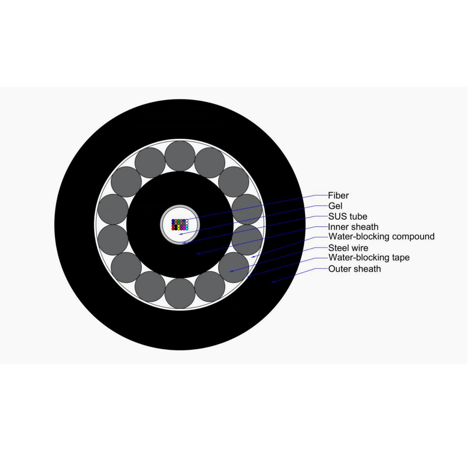
Communication circuits require a different selection process. Copper data cables may be practical for shorter onboard networks, but optical fiber provides high-capacity transmission without conducting electrical current. An Offshore Fiber Optic Cable combines optical fibers with water-blocking components, strength members, armor, and an outer sheath for offshore and underwater communication routes. Armor configuration must be chosen according to installation tension, water depth, seabed conditions, external aggression, and recovery requirements rather than bandwidth alone.
Power circuits range from small auxiliary loads to medium- and high-voltage transmission systems. Their design must consider continuous current, voltage drop, insulation level, short-circuit forces, grouping, ambient temperature, and thermal conditions around the route. Submarine power systems introduce additional concerns such as pulling tension, bending limits, water pressure, seabed movement, external impact, and repair access. Treating shipboard distribution cable and subsea export cable as interchangeable products can therefore produce serious technical and commercial risks.
How Construction Layers Protect Performance
Cable performance comes from the complete construction, not from the outer jacket alone. The conductor carries electrical current, while optical fibers transmit light signals in communication cables. Insulation separates energized conductors and must tolerate the specified voltage, temperature, and electrical stress. Fillers, tapes, and inner coverings maintain cable geometry and create a stable foundation for shielding or armor. International marine cable standards address construction and testing for fixed power, control, and instrumentation cables used on ships and offshore units, as well as the characteristics of insulating and sheathing materials.
Shielding and armor perform different jobs. A copper braid, foil screen, or other metallic shield helps control electromagnetic interference and provides a defined path for induced currents when correctly grounded. Armor primarily protects against pulling forces, impact, crushing, fishing activity, anchoring hazards, and other mechanical loads. Depending on the design, armor may also contribute to grounding or fault-current performance, but this must be confirmed rather than assumed. Adding heavy armor without reviewing bending radius, cable weight, termination design, and installation equipment can make a system harder to install and maintain.
Water-blocking layers restrict longitudinal or radial water migration after sheath damage. Bedding separates metallic layers, while the outer sheath resists environmental exposure and handling damage. The HV Submarine Cable range includes copper or aluminum conductor options, XLPE insulation, water-blocking layers, and steel wire or steel tape armor. Listed voltage options extend from 66 kV to 400 kV, with single-core and three-core configurations. Project engineers must still coordinate conductor design, bonding, losses, thermal rating, installation tension, accessories, and route conditions as one cable system.
No material is universally superior in every location. XLPE may provide suitable electrical and thermal properties for many power applications, while PVC, PE, rubber compounds, and low-smoke zero-halogen materials serve different environmental and fire-performance needs. The correct sheath depends on oil exposure, sunlight, abrasion, water contact, temperature, flexibility, and combustion requirements. Material names should therefore be connected to documented test performance and operating conditions, not treated as standalone guarantees.
Selecting Marine Cable for Offshore Applications
The most reliable specification begins with the application and installation route. Engineers should define circuit duty, exposure, movement, fire zone, hazardous-area status, mechanical loads, required approvals, and expected maintenance access before comparing cable constructions. Offshore projects may also require classification approval, product certification, design-document review, and an installation survey.
Marine Automation
Marine automation cable selection should focus on signal integrity and predictable termination. Variable-frequency drives, motors, contactors, radio equipment, and high-current feeders can introduce electrical noise into nearby control circuits. Shield type, pair or core arrangement, grounding practice, and physical separation must work together to manage interference. Engineers should also review conductor flexibility, cabinet entry space, identification, bend radius, and gland compatibility because a technically suitable cable can still become unreliable when installed with poor routing or terminations.
Offshore Energy and Wind Farms
Offshore energy projects use several marine cable families within one system. Array and export cables transmit power, optical elements support communication and monitoring, and control cables connect switchgear, sensors, turbines, substations, and protection systems. Cable design must account for seabed conditions, burial strategy, free spans, thermal properties, installation vessel limits, and interfaces with foundations or offshore substations. Concept design, manufacturing, testing, transport, installation, commissioning, operation, maintenance, and decommissioning should be treated as connected stages of subsea cable risk management.
Oil and Gas Platforms
Oil and gas platforms add hydrocarbons, drilling fluids, hazardous areas, high equipment density, and demanding shutdown requirements. Cable selection should address chemical resistance, fire performance, mechanical protection, electromagnetic compatibility, and the area-classification requirements of the installation. Hazardous-area cable entries, glands, grounding, and installation methods must remain consistent with the certified equipment and protection concept.
Subsea and Interconnection Routes
Subsea routes require more than a voltage or fiber-count specification. Route surveys, water depth, seabed composition, installation tension, cable weight, minimum bending radius, burial depth, crossing design, and external aggression affect the required armor and protection system. Shore approaches and platform pull-ins can create higher mechanical stress than steady-state operation on the seabed. Engineers should also consider repair strategy, spare lengths, jointing procedures, monitoring, and vessel availability because cable accessibility strongly influences lifecycle risk and outage duration.
Installation, Testing, and Lifecycle Reliability
Correct installation preserves the properties built into a marine cable. Routes should avoid sharp edges, excessive heat, chemical leakage, impact zones, and unsupported spans. Power, control, instrumentation, and communication circuits may require separation to reduce interference or protect redundant systems from a common failure. Supports must restrain the cable without crushing it, while glands and penetrations must maintain sealing, strain relief, grounding continuity, and fire-boundary performance. The manufacturer’s pulling tension and minimum bending-radius limits should govern handling throughout storage and installation.
Termination quality is often as important as the cable itself. Incorrect shield bonding can increase noise, poorly prepared insulation can weaken electrical performance, and an incompatible gland may allow moisture entry or fail to secure armor. Installers should use approved accessories sized for the actual cable diameter and construction. Cable ends should remain sealed during storage and pulling, especially in humid or offshore environments. Identification, route records, test reports, and termination drawings also make later inspection and troubleshooting faster and less disruptive.
Testing should be defined before installation begins. Depending on the system, checks may include conductor continuity, insulation resistance, shield continuity, fiber attenuation, phase identification, sheath integrity, grounding, and functional verification. Higher-voltage and subsea systems require project-specific test procedures coordinated with joints, terminations, and connected equipment. Baseline results should be retained so later inspections can identify deterioration rather than relying on isolated pass-or-fail readings. Classification processes may also include equipment approval, design-document review, certification, and a survey after onboard installation.
Maintenance should focus on locations where failure is most likely: glands, joints, exposed deck routes, moving interfaces, support points, penetrations, and areas affected by chemicals or heat. Inspectors should look for sheath cracking, abrasion, corrosion, loose supports, water entry, discoloration, damaged seals, and abnormal test trends. Subsea cable maintenance is less accessible, so route protection, monitoring, installation records, spare strategy, and repair planning become especially important. Lifecycle reliability begins during specification and route design, not after the first fault appears.
Conclusion
Marine cable selection should connect electrical duty with environmental exposure, mechanical loading, fire behavior, installation practice, and approval requirements. Reliable systems result from coordinating cables, glands, joints, supports, grounding, routing, and testing rather than evaluating each item separately. Yongchuang is a manufacturer and supplier offering power, control, communication, waterproof, corrosion-resistant, and submarine cable options for marine automation and offshore applications. Its product range can support better cable matching when specifications are based on verified route and operating conditions.
FAQ
Q: What is the main difference between marine cable and ordinary cable?
A: Marine cable is designed and tested for combinations of moisture, salt, vibration, mechanical stress, fire requirements, and installation conditions commonly found on ships and offshore facilities.
Q: Can every waterproof cable be installed permanently underwater?
A: No. Permanent submersion requires verified water-depth, pressure, water-blocking, mechanical-load, and installation ratings. A general waterproof description does not automatically confirm subsea suitability.
Q: Why is shielding used in marine automation cables?
A: Shielding helps limit electromagnetic interference affecting control, measurement, and communication signals, but performance also depends on grounding, termination, cable layout, and separation from power circuits.
Q: What should be checked before selecting a marine cable?
A: Confirm circuit function, voltage, current, signal type, route conditions, movement, chemicals, fire performance, mechanical loading, bending radius, approvals, accessories, and applicable classification requirements.
Q: Is armor always required for marine cable installations?
A: No. Armor is selected when mechanical protection or tensile strength is needed. Protected indoor routes may use unarmored cable when the project rules and risk assessment permit it.
Q: Which standards are commonly considered for marine cable?
A: The IEC 60092 series covers shipboard cable construction, materials, selection, and installation, while the IEC 61892 series addresses electrical installations on mobile and fixed offshore units.