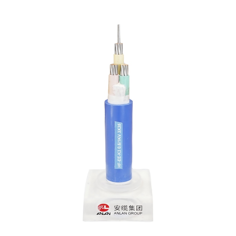
In a nuclear environment, the margin for error is exactly zero. Electrical specification stakes are incredibly high across these facilities. The functional difference between power delivery and system signaling often dictates plant safety. It also guarantees continuous, reliable daily operations. Both cable categories must survive extreme operating conditions. They face intense radiation, immense heat, and aggressive moisture.
Yet, their fundamental engineering approaches differ entirely. Material composition and failure risks share very little overlap. You must understand these distinctions clearly to prevent catastrophic systemic failures. This guide serves as a foundational technical baseline. It helps procurement and engineering teams evaluate complex specifications accurately. You can apply these insights to new builds, immediate retrofits, or long-term plant life-extension projects. We will break down their core functional divides. We will also explore the strict environmental qualification standards governing their deployment.
Key Takeaways
Primary Function: A nuclear power cable transmits high-voltage electrical energy to heavy equipment, while a nuclear control cable transmits low-voltage signals to command systems and instrumentation.
Structural Focus: Power cables prioritize robust conductor sizing and thermal dissipation; control cables prioritize intricate EMI (Electromagnetic Interference) shielding and signal integrity.
Shared Compliance: Both must pass rigorous Environmental Qualification (EQ) protocols, including simulated LOCA (Loss of Coolant Accident) conditions and cumulative radiation exposure.
Procurement Implication: Specifying the wrong shielding or insulation degrades systemic reliability, leading to costly premature aging or regulatory non-compliance.
The Core Functional Divide: Power Transmission vs. System Command
Every facility relies on two distinct electrical pathways to function safely. We can categorize these pathways into bulk energy transmission and precise system signaling. Understanding this functional divide is your first step toward accurate procurement.
Defining the Power Cable
This infrastructure delivers bulk electrical energy throughout the plant. It connects main generators directly to the external grid. It also powers heavy-duty internal plant loads. You will find these robust lines driving primary coolant pumps and massive ventilation motors. They typically operate within medium to high voltage classifications. The engineering prioritizes safe, continuous energy flow under massive electrical loads. A standard industrial power cable might handle similar voltages. However, nuclear variants require vastly superior structural integrity to survive containment zones.
Defining the Nuclear Control Cable
Think of this category as the central nervous system of the facility. It connects critical relays, remote switches, and sensitive instrumentation panels. Operators rely on these circuits to initiate, regulate, or terminate vital processes. These lines transmit low-voltage data rather than high-voltage energy. You cannot swap them for a standard electrical control cable used in regular manufacturing plants. Nuclear environments mandate strict Class 1E safety classifications. This designation ensures the line performs flawlessly during seismic events and severe accidents.
Failure Mode Comparison
Failure consequences highlight the stark differences between these two systems. A power line failure typically triggers a localized equipment trip. It might cause a temporary power loss to a specific pump. The plant often manages this safely using redundant backup generators. Conversely, a nuclear control cable failure creates severe systemic confusion. It can cause erratic instrumentation readings on the main control board. Worse, it might compromise automated safety responses during an active incident. Data corruption here threatens the core reactor safety protocols directly.
Technical Evaluation: Structural and Material Differences
Designers engineer these products using distinct material philosophies. Each component addresses specific environmental stressors and operational demands. We must evaluate their conductors, shields, and insulation layers separately.
Comparison Chart: Structural Attributes
Component
Power Infrastructure
Control Infrastructure
Conductor
Large cross-section, high amperage capacity
Small, multi-conductor, highly flexible
Shielding
Semi-conductive screens for stress control
Copper tape or braided meshes for EMI blocking
Insulation
Thick XLPE/EPR for high thermal thresholds
Thinner, highly calibrated for signal purity
Conductor Sizing and Stranding
Energy delivery requires massive conductor dimensions. Manufacturers utilize large cross-sectional areas of premium copper or aluminum. These designs carry immense amperages safely. They prevent excessive thermal breakdown during peak load periods. In contrast, signal transmission relies on smaller configurations. These bundles feature multiple thin copper conductors. This design optimizes flexibility for tight routing. It also guarantees precise low-voltage signal transmission across long distances.
Shielding and EMI Protection
Electromagnetic interference poses a massive threat to data integrity. A command signal requires complex, specialized shielding. Manufacturers wrap these cores in copper tape or intricate braided shields. This barrier prevents high-voltage background noise from corrupting vital data signals. Power transmission faces different electrical challenges. These massive lines generate interference rather than suffering from it. Their design focuses heavily on semi-conductive screens. These screens manage electrical stress distribution evenly across the insulation layers.
Insulation and Jacketing Systems
Extreme environments require advanced polymer science. Facilities rely heavily on Cross-Linked Polyethylene (XLPE) or Ethylene Propylene Rubber (EPR). Insulation thickness scales directly proportionally to voltage ratings. Heavy power lines require thick barriers to contain electrical energy. Signal lines use thinner but equally durable polymer blends. Both categories demand mandatory Low Smoke Zero Halogen (LSZH) properties. LSZH materials prevent toxic, corrosive gas release during potential facility fires. This protects both human personnel and sensitive electronic equipment.
Navigating Environmental Qualification (EQ) and Safety Standards
Regulatory compliance forms the foundation of facility safety. Every component must pass exhaustive testing before installation. These protocols simulate decades of stress and sudden catastrophic events.
The Baseline: IEEE and IAEA Standards
Industry frameworks dictate strict testing parameters globally. Engineers rely heavily on IEEE 323 for general environmental qualification procedures. They utilize IEEE 383 to govern severe flame testing and accident simulations. The International Atomic Energy Agency (IAEA) also provides overlapping regulatory guidelines. Compliance proves a nuclear power cable can perform its primary safety function under extreme duress.
Radiation Resistance
Polymers degrade when exposed to ionizing radiation. Testing evaluates two separate exposure scenarios. Continuous low-level background radiation represents daily operational wear. Accident-spike radiation simulates a sudden catastrophic release. These events impact insulation polymers differently based on their specific formulations. Heavy energy lines experience outer jacket embrittlement. Sensitive signal lines face severe internal data degradation. Both must maintain complete circuit integrity despite substantial molecular damage.
LOCA/DBA Survivability
The Design Basis Accident (DBA) represents the worst-case scenario. Testing simulates a complete Loss of Coolant Accident (LOCA). The qualification process follows specific harsh criteria:
Superheated Steam Exposure: Components face sudden blasts of extreme temperature steam.
Chemical Spray Submersion: Engineers douse the test subjects in caustic boric acid solutions.
Both categories must maintain absolute circuit integrity during this chaos. However, testing thresholds for signal degradation remain critically tight for control circuits. Even minor impedance changes could trigger false safety protocols.
Implementation Realities: Installation, Routing, and Aging Management
Procuring excellent hardware solves only half the problem. Installation mechanics and long-term maintenance determine true operational success. Engineers face severe physical constraints inside modern containment structures.
Routing and Space Constraints
Laying heavy infrastructure inside containment structures presents massive physical challenges. Space remains severely limited. Engineers must strictly observe minimum bending radius limitations. Large energy lines remain incredibly rigid. They require substantial physical force and specialized equipment to route safely. Multi-conductor signal bundles bend more easily but demand extreme care. Rough handling can easily tear their delicate internal EMI shielding. Damaged shielding immediately voids the Class 1E safety qualification.
Thermal Hotspots and Segregation
Physical separation prevents cascading failures. Regulations require operators to physically separate redundant safety trains. You must never route Train A and Train B through the same penetration points. Furthermore, you must aggressively segregate energy lines from signal lines. High-voltage pathways generate substantial radiant heat and intense EMI. Placing sensitive data bundles too close induces rapid thermal aging. It also risks severe data corruption from electrical noise.
Aging Management (The "Life After 40" Factor)
Many legacy facilities now pursue aggressive life extensions. They push operational licenses from 40 years to 60 or even 80 years. Condition monitoring becomes absolutely critical.
Energy Line Monitoring: Operators typically rely on partial discharge testing. This detects microscopic voids forming inside thick insulation.
Signal Line Monitoring: Technicians utilize Frequency-Domain Reflectometry (FDR). They also use specialized Line Resonance Analysis (LIRA). These tools detect localized embrittlement without destroying the delicate internal conductors.
Decision Framework: Specifying and Shortlisting Your Vendor
Choosing the right manufacturing partner dictates your project timeline and safety compliance. You must evaluate potential vendors beyond simple price sheets. Rigorous documentation and engineering flexibility remain paramount.
Quality Assurance & Traceability
A legitimate partner operates under a recognized, audited quality assurance program. In the United States, this means strict adherence to 10 CFR 50 Appendix B. It also requires compliance with NQA-1 standards. These frameworks ensure total material traceability. If a specific polymer batch fails five years later, you must know exactly where operators installed it. Reject any vendor lacking transparent QA documentation.
Customization vs. Off-the-Shelf
Retrofitting older facilities introduces unique dimensional challenges. Standard footprints no longer fit legacy containment penetrations. You must evaluate whether the vendor can engineer custom multi-conductor combinations. Some projects require blending specific signal gauges into single, slim-profile jackets. Flexible manufacturers adapt their tooling to meet your exact spatial constraints. Off-the-shelf suppliers often force costly structural modifications to the facility itself.
Transparent Testing Data
Never accept a simple "certified" stamp on a specification sheet. You must demand unredacted, comprehensive type-test reports. Review the raw data for thermal aging curves. Examine the exact parameters used during radiation exposure tests. Scrutinize the signal degradation charts recorded during LOCA simulations. Transparent vendors provide this data willingly. It proves their engineering claims hold up under independent, third-party laboratory scrutiny.
Conclusion
Nuclear environments demand absolute electrical perfection. Power transmission systems and system command networks share incredibly strict environmental survival mandates. They both face intense radiation and simulated catastrophic accidents. However, their core engineering priorities dictate completely different specification matrices. Energy lines focus heavily on massive amperage capacity and thermal dissipation. Signal lines prioritize delicate data protection and intricate EMI shielding.
You must audit your current specifications aggressively. Review your inventory against impending plant life-extension timelines. Ensure your legacy infrastructure can survive the demanding "Life After 40" operating reality. We strongly encourage you to consult experienced engineering teams immediately. Request a comprehensive technical review of your existing layouts. Explore custom design options to secure your facility's long-term operational safety.
FAQ
Q: Can a standard electrical control cable be used in a nuclear power plant?
A: No, unless operators install it in a non-safety-related, mild-environment area. The industry refers to this as the Balance of Plant. If you route it inside containment or safety-critical areas, you must use a qualified Class 1E product. Standard industrial components cannot survive radiation or DBA conditions.
Q: How does EMI affect a nuclear control cable compared to a power cable?
A: High-voltage power lines naturally generate EMI during normal operation. Conversely, data lines remain highly susceptible to it. Without proper internal shielding, this external EMI easily induces false signals. This data corruption can cause automated safety systems to behave unpredictably during critical operations.
Q: What is the expected lifespan of nuclear-grade cables?
A: Historically, engineers qualified these components for 40-year lifespans. Today, modern EQ testing yields better data. Advanced polymers, like specialized EPR and XLPE blends, prove highly resilient. They are increasingly validating operational lifespans of 60 to 80 years when supported by proper aging management programs.