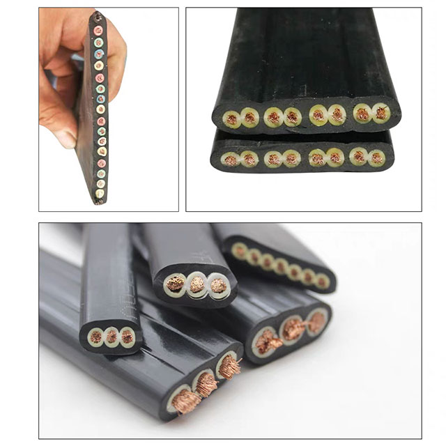
Utilizing standard cables in high-heat environments guarantees accelerated degradation. This oversight leads to unplanned downtime, compliance failures, and severe safety hazards. Industrial operations simply cannot afford these preventable electrical failures. Balancing thermal limits against mechanical durability, chemical exposure, and budget constraints remains a massive procurement challenge. Engineers often struggle to find materials capable of surviving extreme ambient heat while simultaneously handling high electrical loads. It requires a highly systematic approach to avoid costly and dangerous missteps. This guide provides an objective, engineering-focused framework. We evaluate, shortlist, and specify the correct high temperature cable for your exact operational requirements. You will learn how to accurately assess ambient heat factors. We cover how to select appropriate insulation materials based on thermal tolerances. Finally, you will understand how to apply necessary ampacity derating formulas for complete regulatory compliance.
Key Takeaways
Temperature ratings must account for both ambient environmental heat and internal conductor heating (ampacity).
Selecting insulation is a trade-off: Fluoropolymers offer chemical resistance, Silicone provides flexibility, and fiberglass survives extreme peaks.
Regulatory compliance (UL, CSA, NEC) requires accurate ampacity derating calculations for elevated ambient temperatures.
Defining High Temperature Cable Requirements for Your Application
Most standard wiring utilizes PVC or XLPE insulation. These basic materials begin to fail rapidly when ambient temperatures exceed 90°C. They suffer from severe thermal degradation over time. The polymer chains inside the jacket break down under continuous heat exposure. The insulation gradually loses essential plasticizers. It becomes extremely brittle and cracks under minor physical stress. Eventually, you experience a catastrophic dielectric failure. This failure can trigger electrical fires or destroy expensive connected equipment. Finding the right replacement requires establishing a strict temperature baseline.
First, you must define the continuous operating temperature. This metric represents the maximum heat the cable endures continuously over its operational lifetime. You design your primary specification around this number. Next, identify your peak or overload temperature limits. These are short-duration thermal spikes. They often occur during equipment startups or minor system faults. Finally, account for short-circuit conditions. These rare events generate immense heat in mere milliseconds. Your chosen jacket must survive these brief spikes without melting.
You must also evaluate your specific heat sources carefully. We categorize them into two distinct types. You need to measure both accurately to specify the right product.
External Heat: Surrounding environmental factors heavily influence wire performance. These include nearby blast furnaces, combustion engines, or naturally hot ambient climates.
Internal Heat: Conductors generate their own heat. We call this Joule heating. It stems from high current loads running through the copper core.
Both sources combine to determine your total thermal load. A High Temperature Cable must safely dissipate this combined heat. Neglecting internal heat generation remains a very common engineering mistake. Always calculate the additive effect of ambient and internal temperatures.
Comparing Insulation Types for a Thermal Resistant Cable
Matching your thermal baseline to the correct material is critical. Engineers face a clear trade-off during this phase. Different environments demand radically different insulation properties. We outline the primary material options below.
Fluoropolymers (PTFE, FEP, PFA)
Fluoropolymers typically feature continuous ratings between 200°C and 260°C. They offer exceptional chemical resistance against harsh acids and alkalis. Their dielectric properties are completely outstanding. This allows manufacturers to extrude very thin walls. However, they are generally much less flexible than rubbers. They work best for aerospace wiring, chemical processing facilities, and tight-routing sensor applications.
Silicone Rubber
Silicone ratings normally range from 150°C to 200°C. It offers unmatched flexibility in tight spaces. Its cold-temperature performance remains excellent even below freezing. However, silicone is highly vulnerable to certain industrial oils and solvents. It swells and loses integrity upon contact. You often need to specify a fiberglass-braided outer jacket for physical protection. Silicone fits perfectly in robotics, metallurgy plants, and heavy commercial appliances.
EPR Insulated Cable (Ethylene Propylene Rubber)
An EPR Insulated Cable offers continuous ratings from 90°C to 105°C. It can safely survive temporary overloads up to 130°C. It provides superior moisture, corona, and weathering resistance. Standard synthetics simply cannot compete against its rugged nature. EPR proves highly reliable for buried utilities, mass transit networks, and heavy industrial power distribution grids.
Fiberglass, Mica, and Ceramic
These specialized materials offer extreme thermal survival capabilities. Ratings stretch from 400°C to well over 1000°C. They exhibit very low physical flexibility. They serve highly specific, specialized roles. You primarily find them in steel mills, foundries, and industrial kilns. They resist direct flame contact for extended periods.
Insulation Type Comparison Matrix
Material Family
Continuous Temp Range
Key Advantages
Common Applications
Fluoropolymers
200°C - 260°C
Chemical resistance, thin profile
Aerospace, chemical plants
Silicone Rubber
150°C - 200°C
Extreme flexibility, cold resistant
Robotics, consumer appliances
Ethylene Propylene Rubber
90°C - 105°C
Moisture and weathering resistance
Utilities, transit networks
Fiberglass & Mica
400°C - 1000°C+
Absolute extreme heat survival
Steel mills, industrial kilns
Beyond Heat: Secondary Evaluation Dimensions
Heat never exists in a vacuum inside a factory. You must evaluate multiple secondary environmental and physical dimensions. Failing to assess these factors ruins otherwise well-specified wiring. A highly capable Thermal Resistant Cable needs much more than just a high melting point.
Environmental Exclusions
Always assess the presence of aggressive chemicals in your facility. Splashing hydraulic fluids and industrial solvents degrade weak jackets instantly. UV radiation breaks down certain rubbers very quickly during outdoor use. Constant moisture and petroleum-based oils degrade standard compounds over time. You must factor these exclusions into your final material choice. A wire might survive 200°C perfectly but fail instantly when exposed to machine oil.
Mechanical Stress & Routing
Physical demands destroy cables just as fast as extreme heat. You must match the physical limits of the wire to the surrounding installation environment. Consider the following mechanical threats carefully.
Abrasion Resistance: Does the routing drag across rough metal surfaces? Fluoropolymers handle scrapes well, while soft silicone tears easily.
Vibration Tolerance: Constant movement hardens some materials. You need high-strand-count copper cores to survive heavy engine vibration.
Minimum Bend Radius: Thick, rigid insulations cannot navigate tight corners. Forcing a tight bend fractures the internal dielectric shield.
Electrical Demands
Electrical properties often shift under extreme heat. Verify your voltage ratings carefully against operating temperatures. Dielectric strength requirements change based on ambient conditions. You may also need specific shielding layers to prevent Electromagnetic Interference (EMI). Shielding protects sensitive sensor loops and precision control circuits. Heat can degrade standard copper shielding, so specify nickel-plated copper for extreme zones.
Navigating Ampacity Derating and Industry Compliance
Heat directly impacts how much current a wire can carry safely. You must understand the ampacity derating imperative thoroughly. As ambient temperature rises, a cable’s current-carrying capacity drops significantly. You cannot push standard current through a hot wire.
If you ignore this natural drop, the internal conductor overheats rapidly. You must use NEC (National Electrical Code) correction factors. These standard formulas help you calculate the exact safe current limit. They adjust your baseline ampacity downward for elevated ambient temperatures. A wire rated for 50 amps at room temperature might only carry 30 amps safely at elevated levels. Proper calculations prevent internal jacket fires.
Regulatory Lenses (UL, CSA, CE)
Verified compliance ratings matter immensely in commercial environments. They protect your corporate liability and maintain active insurance coverage. They also guarantee fundamental facility safety. You must look for strict UL, CSA, or CE marks. An untested wire presents a massive fire risk. Inspectors will immediately red-tag unverified installations. Never install non-compliant wiring in critical infrastructure zones.
Verification and Testing
Never rely on basic catalog summaries or brief marketing brochures. We strongly recommend requesting full material data sheets. Always ask your supplier for independent third-party testing certifications. Secure these technical documents before making a final specification. This crucial step validates the safety of your entire installation. It removes the guesswork from harsh environment engineering.
Implementation Realities and Installation Pitfalls
Even the best materials fail if technicians install them incorrectly. Field implementation carries unique physical risks. You must plan for actual installation realities from day one. Many systems fail at connection points rather than along the main run.
Connector Compatibility
Many engineers pair a specialized wire alongside standard terminations. This creates a severe thermal bottleneck. Your connectors and metal lugs must meet the exact thermal rating of the selected insulation. They must ideally exceed it. Standard plastic connectors melt long before the specialized jacket fails. Always specify high-heat terminals, heavy-duty crimps, and appropriate heat-shrink tubing.
Pulling and Routing Stress
Installation crews often damage specialized wiring during initial pulls. Certain high-temp insulations require careful, highly specialized handling. Fiberglass braids fray easily if technicians pull them roughly through conduits. Thick fluoropolymers resist bending and can crease permanently. You must prevent jacket damage during the entire routing process. Ensure your team uses correct lubricants and gentle pulling techniques. Use appropriately sized conduit bends to avoid crushing the core.
Standard vs. Custom Solutions
You face a continuous choice between off-the-shelf and custom wire designs. Sometimes, a standard catalog wire works perfectly for minor applications. However, complex environments often demand custom-engineered composite options. A custom build actively solves multiple environmental challenges simultaneously. It reduces the frequency of replacements in extremely harsh zones. By upgrading to a specialized build, you streamline maintenance schedules. You also significantly improve overall facility uptime and operational reliability.
Conclusion
Selecting proper wiring requires a strict, logical, and evidence-based approach. Summarizing the evaluation funnel simplifies this complex process. First, define your maximum continuous and peak temperatures accurately. Next, calculate your ampacity derating correctly using standard NEC correction tables. Identify all mechanical stresses and chemical hazards present in the facility. Then, select the specific insulation material matching these exact threats. Finally, verify all compliance ratings and request independent testing certifications.
These actionable steps actively prevent premature field failures. Do not guess when specifying materials for extreme environments. We encourage you to consult directly with experienced application engineers. Discuss your specific thermal and chemical constraints in detail. Request a technical consultation today. Download a comprehensive specification datasheet to review your options thoroughly. Alternatively, submit a detailed RFQ outlining your exact environmental parameters.
FAQ
Q: How do I calculate ampacity derating for high temperature cables?
A: You must use NEC ampacity tables based on your specific ambient temperature. First, find the baseline ampacity for your conductor size. Then, locate the required correction factor for your elevated ambient heat. Multiply the baseline ampacity by this specific correction factor. This provides your safe, adjusted operating current limit.
Q: What is the difference between FEP and PTFE insulation?
A: The main difference involves their thermal limits and extrusion methods. FEP operates safely up to 200°C and extrudes easily into continuous lengths. PTFE withstands temperatures up to 260°C. However, manufacturers must tape or ram-extrude PTFE. This production method limits continuous length capabilities and slightly reduces overall flexibility.
Q: Can EPR Insulated Cable be used in submerged or wet applications?
A: Yes, it performs exceptionally well in wet environments. Ethylene Propylene Rubber features excellent dielectric stability directly in water. It resists moisture absorption far better than standard PVC jackets. This makes it highly reliable for submerged utility lines and outdoor industrial routing.
Q: Why is my high-temperature wire failing prematurely?
A: Premature failure usually stems from unassessed environmental blind spots. You might have chemical incompatibility breaking down the outer jacket. Mechanical abrasion might be wearing entirely through the insulation. Alternatively, localized heat spikes and internal joule heating might exceed the original specifications. Always audit the entire operational environment carefully.