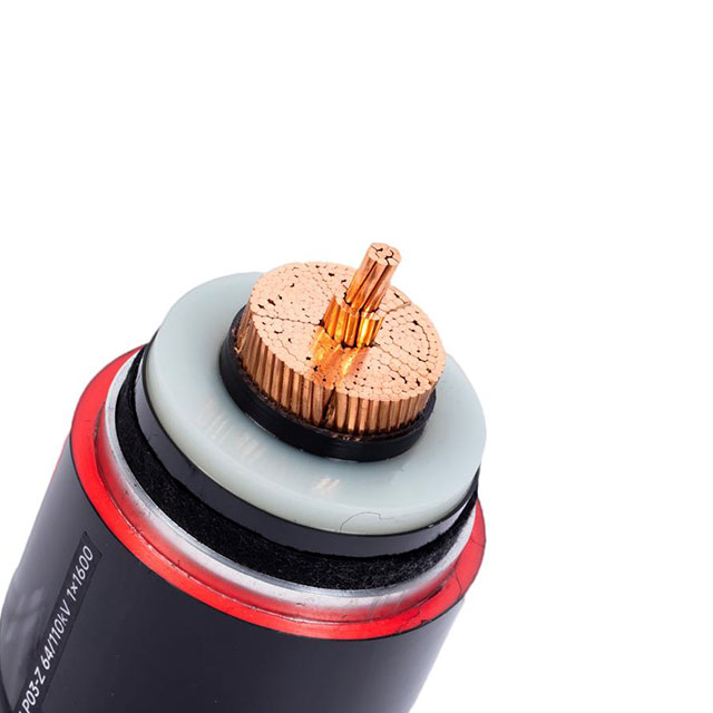
Upgrading grid infrastructure requires precise engineering decisions. You must balance initial system design against long-term transmission efficiency. Long-haul industrial power networks depend heavily on accurate capacity scaling. Misaligning cable capacity creates severe problems for project execution. Under-speccing leads to massive energy losses along the transmission route. Conversely, over-speccing creates an unjustified infrastructure scale and unnecessary physical footprint.
We need a clear, evidence-based framework for evaluating standard high voltage options against ultra-high voltage alternatives. This article establishes that framework for your engineering team. You will learn how to assess distance, load capacity, and grid compatibility accurately. We explore the distinct thresholds separating these advanced technologies. You will discover structural differences, insulation requirements, and thermal management protocols. Finally, we highlight implementation risks and compliance realities to guide your next major grid project safely.
Key Takeaways
Voltage Thresholds: HV generally spans 35 kV to 345 kV; UHV is defined as 800 kV and above for Direct Current (DC) and 1000 kV and above for Alternating Current (AC).
Primary Application: HV cables serve regional grids and heavy industrial complexes; UHV cables are strictly for cross-regional, massive-scale power transmission.
Efficiency vs. Cost: UHV drastically reduces $I^2R$ (line) losses over hundreds of kilometers but requires complex, high-cost specialized substations and terminations.
Structural Demands: UHV requires exponentially stricter insulation, shielding, and thermal management protocols compared to standard HV.
Defining the Baseline: High Voltage vs. UHV Thresholds
Engineers rely on strict voltage classifications to design modern power grids. Industry standards established by the International Electrotechnical Commission (IEC) provide clear boundaries. These boundaries prevent dangerous misapplications of electrical equipment. Understanding these parameters ensures system stability across diverse geographical deployments.
We define a standard HV Cable as operating between 35 kV and 345 kV. Engineers typically utilize these cables for municipal transmission rings. They also serve as the primary links for offshore wind farm connections. Heavy manufacturing facilities often require these lines for direct grid tie-ins. The infrastructure required for this category remains widely standardized. Equipment procurement is highly predictable across global markets.
Conversely, Ultra High Voltage operates on a vastly different scale. Regulations classify UHV parameters as 800 kV and above for Direct Current (DC) systems. For Alternating Current (AC) systems, the threshold sits at 1000 kV and above. Engineers purpose-build these lines for macro-grid interconnections. They transmit multiple gigawatts of power over distances exceeding 1000 kilometers. This extreme voltage minimizes energy loss across vast continental divides.
We must also clarify the Extra High Voltage (EHV) bridge. EHV spans the 345 kV to 765 kV gap. Understanding EHV prevents classification confusion during project planning. EHV systems handle loads too large for standard municipal grids but do not require the extreme infrastructure of true macro-grid interconnects.
Voltage Classification Reference Matrix
Classification Category
Voltage Range (AC)
Primary Application Area
High Voltage (HV)
35 kV to 345 kV
Municipal rings, industrial grid tie-ins
Extra High Voltage (EHV)
345 kV to 765 kV
Intra-regional bulk transmission
Ultra High Voltage (UHV)
≥ 1000 kV
Cross-continental macro-grid connections
Core Structural and Engineering Differences
Moving electricity at extreme voltages physically alters the demands placed on materials. Manufacturers engineer UHV Cable systems using fundamentally different philosophies than standard regional lines. Insulation, shielding, and heat management require completely distinct approaches.
Insulation Technologies
Standard networks predominantly rely on Cross-Linked Polyethylene (XLPE). XLPE offers an excellent, stable balance of thermal tolerance and flexibility. It resists moisture penetration and handles routine load cycling effortlessly. For regional grids, XLPE provides decades of reliable dielectric strength.
Macro-grid interconnections demand highly specialized insulation. Extreme electrical stress easily degrades standard polymers. To prevent dielectric breakdown, designers often implement advanced oil-filled systems. Gas-insulated line (GIL) structures using sulfur hexafluoride or nitrogen mixtures offer another robust solution. When using solid polymers for these extreme loads, manufacturers must produce state-of-the-art, ultra-pure XLPE compounds in surgically clean extrusion environments.
Conductor Design and Shielding
Cross-sectional areas differ significantly to manage alternating current behaviors. The skin effect pushes current toward the outer edge of a conductor. Engineers mitigate this by utilizing segmented Milliken conductors for massive load requirements. These complex geometries balance thermal loads and reduce resistance.
Enhanced metallic shielding remains critical for extreme setups. Massive electromagnetic fields (EMF) surround these lines. Shielding structures must safely redirect severe fault currents away from sensitive equipment. Stronger metallic screens and heavier lead sheathing protect the surrounding environment from interference.
Thermal Dissipation Protocols
Heat management dictates system longevity. Operating massive interconnections generates substantial thermal output. Standard regional lines often dissipate heat naturally through direct earth burial or standard duct banks. Extreme load applications change this reality entirely.
These massive lines often require active cooling considerations. Engineers design heavily engineered trenching environments utilizing specialized thermal backfill materials. Sometimes, they incorporate integrated water-cooling pipes alongside the primary lines. Without aggressive heat dissipation, the insulation will degrade rapidly.
Best Practices in Thermal Management:
Always conduct a soil thermal resistivity test before trenching.
Use forced-air cooling in subterranean utility tunnels.
Space parallel circuits adequately to prevent mutual heating.
Performance Evaluation: Transmission Distance and Line Loss
Evaluating performance requires understanding the fundamental physics of electricity. The immutable laws of physics dictate every major grid decision. System efficiency hinges entirely on the relationship between voltage, current, and distance.
Power transmission follows a simple equation: Power equals Voltage multiplied by Current. To transmit a massive megawatt capacity, you can either increase the voltage or increase the current. Pushing high current through any conductor generates massive friction, leading to heat. This phenomenon creates $I^2R$ loss, where energy vanishes as thermal radiation. By elevating the voltage to extreme levels, we drastically lower the current. Lower current directly reduces heat generation and preserves raw energy.
We must establish optimal distance ratios for these systems. A standard Power Transmission Cable operates highly efficiently for short to medium-haul routes. When transmitting power under 300 kilometers, standard parameters provide excellent energy retention. Pushing these standard lines beyond 500 kilometers results in prohibitive energy loss.
Upgrading to massive macro-grid thresholds becomes mathematically viable over vast expanses. When moving gigawatts of energy across 1000 kilometers, extreme voltage minimizes loss. Using standard lines for this distance would bleed away a massive percentage of the generated energy before reaching the destination city.
Grid stability also plays a vital role. AC systems require careful synchronization of frequencies across regions. Extremely long AC lines suffer from reactive power accumulation and capacitance issues. This instability often forces engineers toward DC transmission for distances exceeding 800 kilometers. DC lines do not suffer from reactive power loss, making them ideal for uninterrupted point-to-point energy delivery.
Infrastructure Realities and Operational Demands
Deploying major electrical networks requires a thorough understanding of physical infrastructure scale. A High Voltage Cable integrates smoothly into existing municipal grids. Macro-grid deployments, however, demand entirely new physical landscapes and specialized operational frameworks.
Initial Infrastructure Setup
Standard regional grids benefit from highly standardized equipment. Utility companies utilize conventional substation layouts. Termination kits and splicing tools remain readily available across global markets. Engineers can route these lines through existing urban utility corridors or standard overhead towers.
Macro-grid interconnects require massive physical setups. Converting AC power to extreme DC voltages requires highly specialized converter stations. These facilities occupy massive tracts of land. The right-of-way footprints expand significantly to accommodate safety clearances. Constructors must build custom-engineered towers to support immense mechanical loads. In urban areas, these lines often demand deep subterranean tunnels, requiring extensive tunnel-boring operations.
Ongoing Operational Requirements
Long-term operation dictates the true viability of a grid network. Extreme macro-grids excel in energy retention over decades of continuous operation. They deliver massive power loads reliably across continents. However, inspecting and maintaining these specialized components requires highly trained experts. The equipment operates under immense stress, demanding rigorous monitoring systems.
Standard regional grids require more frequent physical maintenance. Environmental factors like ground movement and moisture impact these lines regularly. Despite this, maintenance relies on a broad, accessible pool of engineering labor. Replacement parts sit readily in local utility warehouses. Crews can isolate and repair faults rapidly without specialized cross-border logistics.
Common Mistakes in Infrastructure Planning:
Failing to secure proper land acreage for large-scale converter stations.
Underestimating the specialized labor required for advanced splicing operations.
Ignoring the physical clearance limits necessary for massive overhead towers.
Implementation Risks and Compliance Considerations
Executing a massive transmission project introduces severe implementation risks. Environmental regulations govern how and where you can deploy lines. Strict compliance frameworks dictate every stage of engineering.
Installation complexity presents the largest immediate risk. Jointing and terminating extreme lines demand surgically clean environments. A minor microscopic void or a single speck of dust inside the insulation leads to catastrophic failure. High electrical stress will exploit any imperfection, causing rapid dielectric breakdown. Standard regional lines also require strict tolerances, but they remain slightly more forgiving to environmental installation factors.
Environmental and Right-of-Way (RoW) approvals heavily dictate project timelines. Electromagnetic field (EMF) radiation regulations strictly limit where you can build massive transmission corridors. Authorities heavily scrutinize the visual and spatial impact of towering infrastructure. Gaining public approval for these corridors often takes years of public hearings and environmental impact studies.
Standard regional lines offer much greater routing flexibility. Engineers easily navigate them through urban or semi-urban environments. They utilize existing municipal easements, significantly speeding up the approval process.
Supply chain vulnerability also threatens massive deployments. The pool of globally certified manufacturers capable of producing extreme transmission lines remains remarkably small. Facilities equipped with the vertical extrusion towers needed for perfect insulation are rare. Consequently, securing these materials involves significant lead times. Project managers must anticipate manufacturing delays and severe logistical challenges when moving massive cable drums across oceans.
How to Choose the Right Power Transmission Cable for Your Project
Selecting the optimal transmission infrastructure requires a structured, logical approach. You must eliminate feature preference and rely entirely on physical geography and electrical load requirements.
Evaluation Framework
Step 1: Capacity and Distance Calculation. You must determine the exact load and physical distance. If your load exceeds 3000 MW and your distance surpasses 1000 km, extreme voltage infrastructure becomes necessary. If your parameters fall below this, a macro-grid setup is likely physical overkill.
Step 2: Substation Capability. Assess the local receiving grid. Can the regional substation handle a massive step-down process? Injecting gigawatts of power requires robust regional distribution networks to disperse the energy safely.
Step 3: Resource and Lead Time Alignment. Evaluate your timeline. Custom macro-grid lines require specialized manufacturing runs and long wait times. Standard lines offer faster procurement cycles and quicker deployment.
Shortlisting Logic
Specify standard XLPE systems for intra-city distribution and regional industrial parks. These systems offer fast deployment and excellent reliability. Escalate your design to EHV when bridging power between neighboring states or connecting massive offshore wind arrays to a mainland grid. Commission a custom macro-grid line only when transporting bulk power from remote hydroelectric dams or desert solar farms to distant coastal cities.
Next Steps
Never finalize a transmission class based on initial assumptions. We strongly recommend commissioning a third-party feasibility study. Execute a comprehensive load-flow analysis. Understand your thermal limitations and soil conditions. Only after establishing these hard data points should you issue a Request for Proposal (RFP) to certified manufacturers.
Conclusion
The decision between standard and extreme voltage limits is dictated by the immutable laws of physics and project geography.
Distance and load capacity remain the only accurate indicators for scaling transmission infrastructure.
Extreme voltage significantly reduces line loss over massive distances but demands complex converter stations and vast physical footprints.
Standard regional lines offer superior routing flexibility, standardized equipment, and easier maintenance cycles.
Always prioritize long-term physical efficiency models over rapid deployment assumptions. Misjudging your required capacity creates severe operational headaches for decades. Contact experienced electrical engineering consultants immediately. Utilize specialized procurement teams to review your technical specifications before committing to a grid topology.
FAQ
Q: What is the difference between MV (Medium Voltage) and HV cable?
A: Medium Voltage (MV) generally handles localized electrical distribution. It operates between 1 kV and 35 kV. Utility companies use MV to route power through residential neighborhoods before handing it off to commercial facilities. HV handles bulk regional transmission, moving power between major substations before stepping it down to MV.
Q: Can UHV cables be buried underground like standard HV cables?
A: Direct burial is highly restricted due to severe heat generation and insulation limits. Extreme macro-grid lines require advanced Gas-Insulated Line (GIL) systems or specialized subterranean tunnels. These tunnels must include heavily engineered active cooling systems to prevent catastrophic thermal breakdown.
Q: Are standard High Voltage Cables used in EV infrastructure?
A: No. Automotive "HV" cables inside electric vehicles usually operate between 400V and 800V. This automotive terminology overlaps with grid terminology. Grid-level transmission lines operate at tens or hundreds of thousands of volts and serve entirely different structural and physical purposes.
Q: What is the life expectancy of a UHV vs. HV transmission line?
A: Both baseline lifespans typically exceed 40 years. However, actual longevity depends heavily on continuous thermal cycling and environmental stress. Standard lines often face more localized environmental damage, while extreme lines require specialized maintenance to prevent dielectric degradation over their operational lifespan.