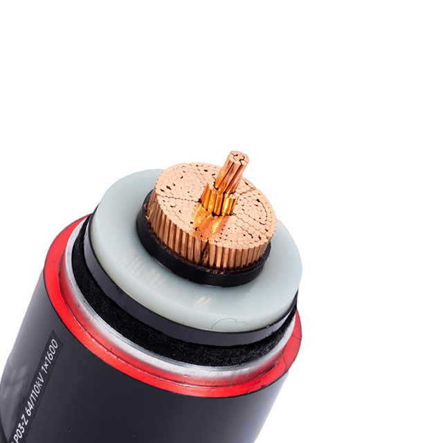
Transitioning from overhead to underground infrastructure represents a high-stakes capital allocation. This shift requires rigorous technical and financial justification. Urban expansion and extreme weather vulnerabilities rapidly push utilities toward grid modernization. Stringent regulatory demands further accelerate the adoption of buried power lines. Concealed systems shield critical power flow from surface-level disruptions. However, making this transition introduces complex engineering and thermal challenges.
We provide engineering and procurement decision-makers with a practical, objective framework. You will learn how to properly evaluate, specify, and deploy the right Underground High Voltage Cable systems. This guide outlines essential technology classifications, strategic adoption drivers, and critical risk mitigation tactics. We explore strict IEC standards and vendor evaluation metrics. By applying these insights, your next grid modernization project can meet stringent performance benchmarks safely and efficiently.
Key Takeaways
CAPEX vs. OPEX: While initial installation costs for underground lines are significantly higher than overhead, long-term OPEX reductions through minimized weather-related outages often justify the ROI in dense or vulnerable environments.
Technology Shifts: XLPE (Cross-linked Polyethylene) has largely superseded fluid-filled designs, offering superior thermal performance and lower maintenance complexity.
Risk Mitigation: Successful deployment hinges on accurate soil thermal resistivity analysis, precision splicing, and compliance with strict IEC/IEEE testing protocols.
Sourcing Criteria: Vendor shortlists must prioritize certified partial discharge testing capabilities and verifiable track records in comparable geographic conditions.
Strategic Drivers for Underground Power Cable Adoption
Grid planners face mounting pressure to modernize aging power transmission networks. They must balance growing capacity needs against severe spatial constraints. Burying electrical infrastructure solves several critical roadblocks. We can group these strategic drivers into three main categories.
Urbanization and Right-of-Way (ROW) Constraints: Dense cities severely limit new overhead paths. Securing land for large transmission towers becomes financially and legally impossible in metropolitan zones. Burying lines along existing transportation corridors bypasses these spatial limitations. Planners can navigate tight urban grids effectively.
Grid Resilience Metrics: Utilities must quantify infrastructure reliability. They track the System Average Interruption Duration Index (SAIDI) and System Average Interruption Frequency Index (SAIFI). Insulating infrastructure from high-wind, heavy ice, and wildfires drastically reduces these failure metrics. Subterranean systems remain insulated from atmospheric volatility.
Permitting and Aesthetic Mandates: Local communities frequently resist overhead transmission corridors. Giant steel structures impact property values and natural landscapes. Burying infrastructure addresses these local regulatory pressures directly. It removes visual pollution and expedites the municipal permitting process.
By focusing on these drivers, project managers build stronger business cases. They prove the long-term value of underground networks despite the heavy initial investment.
Classifying HV Cables for Specific Transmission Environments
Selecting the correct dielectric insulation and conductor material dictates system longevity. Engineers must match the specific cable architecture to the operating environment. Today, we primarily evaluate two distinct insulation technologies.
Cross-Linked Polyethylene (XLPE)
XLPE represents the modern industry standard. It features a robust solid dielectric insulation mechanism. Manufacturers utilize this technology for Extra High Voltage (EHV) lines up to 500kV. It boasts exceptionally low dielectric loss. Most importantly, XLPE carries zero fluid-leakage risk. Maintenance crews prefer it because it requires minimal routine upkeep. This makes it ideal for sensitive environmental areas.
Fluid-Filled (Oil-Filled) Cables
Fluid-filled variants rely on paper insulation. This paper is impregnated with dielectric fluid under pressure. Historically, they dominated high-capacity routes. Today, they serve mostly as legacy systems. Utilities specify them strictly for highly specific legacy-compatibility projects. The industry is generally phasing them out in new deployments. The environmental containment risks of leaking oil are simply too high.
Matching Cable to Application
Beyond insulation, engineers evaluate conductor materials carefully. Copper offers higher conductivity and a smaller cross-sectional area. Aluminum provides a lighter, more cost-effective alternative. You must weigh these options against target ampacity requirements. Evaluating daily load duration curves ensures the chosen HV Cable does not overheat during peak demand spikes.
Table 1: Dielectric Technology Comparison
Feature
XLPE (Solid Dielectric)
Fluid-Filled (Paper/Oil)
Insulation Type
Cross-linked synthetic polymer
Kraft paper and pressurized oil
Maintenance Needs
Very Low
High (pressure monitoring)
Environmental Risk
None
High (potential oil leaks)
Primary Use Case
Modern standard (up to 500kV)
Legacy system extensions
Overhead vs. Underground Transmission Cables: Economic and Efficiency Factors
Project sponsors must evaluate the full financial lifecycle of a transmission asset. Shifting lines below ground alters the capital and operational dynamics entirely. A surface-level cost comparison often misleads decision-makers.
Initial Capital Expenditure (CAPEX)
You must acknowledge the massive installation premium. Undergrounding carries a 5x to 10x CAPEX multiplier compared to aerial lines. This premium stems from complex civil engineering requirements. Crews must perform deep trenching in congested areas. They build reinforced duct banks and large concrete vaults. Furthermore, specialized jointing labor drives up initial procurement and installation costs significantly.
Operational Expenditure (OPEX) & Maintenance
The financial narrative changes during the operational phase. Subterranean systems generate substantial OPEX offsets over time. Utilities eliminate constant vegetation management programs. They avoid expensive emergency storm-damage repairs. Furthermore, visual inspection frequency drops drastically. You save thousands of labor hours annually.
Zero Tree Trimming: Eliminates cyclical vegetation clearing budgets entirely.
Reduced Storm Patrols: Negates the need for post-hurricane helicopter inspections.
Asset Protection: Shields the infrastructure from vehicular accidents and vandalism.
Transmission Efficiency
Electrical efficiency dictates the system's viability over long distances. Underground lines exhibit high capacitance. This generates a unique capacitive charging current. This current consumes the cable’s ampacity. Over long distances, it limits the amount of real power delivered to customers. Therefore, engineers must design reactive power compensation stations. You typically place these shunt reactors at regular intervals. Factoring this into the deployment plan ensures the Transmission Cable maintains optimal power transfer limits.
Navigating Implementation Risks and Lifecycle Limitations
Subterranean grids are not inherently flawless. Burying infrastructure solves weather-related risks but introduces hidden thermal and operational vulnerabilities. Addressing these limitations early prevents catastrophic mid-lifecycle failures.
Thermal Dissipation Challenges
Aerial lines dissipate heat directly into the ambient air. Buried lines rely entirely on the surrounding soil for cooling. Soil thermal resistivity creates a massive bottleneck for ampacity. If the earth cannot absorb the heat, the insulation degrades rapidly. Engineers must execute rigorous thermal surveys. Strategies include selecting specialized backfill materials. Thermal sand and fluidized thermal backfill (FTB) significantly improve heat transfer away from the conductor.
Splicing and Jointing Complexities
The cable itself rarely fails. Cable joints and terminations act as the primary points of failure. Splicing Extra High Voltage lines requires immense precision. Impurities as small as a human hair cause partial discharge. The necessity for highly certified installation technicians is non-negotiable. They must operate in climate-controlled, dust-free clean rooms during the splicing process. Cutting corners here guarantees future blowouts.
Fault Location and Repair Times (MTTR)
Transparency is vital regarding Mean Time To Repair (MTTR). Locating underground faults proves exceedingly difficult. You cannot simply drive a truck down the line to spot a broken wire. Technicians rely on complex time-domain reflectometry (TDR) to pinpoint electrical faults. Once located, the extended downtime begins. Repair teams must excavate the street, remove the damaged section, and perform re-splicing. This process takes weeks, compared to hours for overhead repairs.
Best Practices for Implementation Mitigation
Conduct continuous soil sampling along the entire proposed route.
Mandate a controlled, temporary clean-room tent for all jointing operations.
Install distributed temperature sensing (DTS) fiber optics alongside the Underground Power Cable.
Common Mistakes to Avoid
Assuming uniform soil thermal resistivity across a five-mile trench.
Mixing termination accessories from different, incompatible manufacturers.
Failing to account for future ambient heat generated by parallel utility lines.
Compliance, Standards, and Vendor Shortlisting Logic
Procuring high-voltage materials requires a rigid filtering process. The stakes are too high for unverified components. You must enforce strict adherence to global engineering standards.
Industry Standards
Ensure proposed solutions strictly adhere to IEC 62067. This standard governs solid extruded dielectric systems above 150kV up to 500kV. It dictates precise electrical, mechanical, and thermal thresholds. For North American deployments, equivalent IEEE and EPRI testing protocols apply. Non-compliant materials present severe safety hazards to grid operators.
Factory Acceptance Testing (FAT)
Routine testing separates tier-one manufacturers from lower-quality suppliers. Factory Acceptance Testing (FAT) is entirely non-negotiable. You must witness high-voltage withstand tests firsthand. Furthermore, partial discharge (PD) measurements are critical. PD testing detects microscopic voids within the XLPE insulation. If a manufacturer cannot provide certified, low-background-noise PD test environments, disqualify them immediately.
Evaluation Matrix for Procurement
Next steps for project managers involve aggressive vendor vetting. Always request historical type test certificates. Evaluate the manufacturer's supplied jointing accessories carefully. You must ensure total system compatibility rather than mixing cheaper third-party components. Finally, review their post-installation testing capabilities. A trusted vendor supports on-site commissioning.
Vendor Procurement Evaluation Matrix (Chart)
Evaluation Criteria
Minimum Requirement
Tier-One Indicator
Standard Compliance
IEC 62067 / IEEE equivalent
Active participation in standard committees
FAT Capabilities
Basic HV withstand testing
In-house shielded Faraday cage for PD tests
Accessory Ecosystem
Provides basic joints
Manufactures proprietary, pre-molded joints
Track Record
5+ years in local market
Decades of verified EHV operating data
Conclusion
Investing in a buried high-voltage network resolves critical right-of-way bottlenecks. It shields local communities from environmental vulnerabilities and severe weather disruptions. However, it introduces strict thermal constraints and demanding installation protocols. You must manage these variables precisely.
Success relies on looking far beyond the base material cost. Project leaders must evaluate the entire system lifecycle objectively. This includes everything from trench backfill engineering to the long-term reliability of terminal joints. A poorly executed splice ruins the finest dielectric materials.
Consult with structural and electrical engineering teams immediately. Conduct a site-specific soil thermal survey before finalizing route designs. Request verified financial models and historical failure rate data from shortlisted cable manufacturers. Moving forward with these rigorous standards guarantees a resilient, future-proof transmission grid.
FAQ
Q: What is the standard life expectancy of an underground high voltage cable?
A: Modern XLPE cables are typically engineered for a design life of 40 to 50 years. This assumes proper thermal management throughout the installation. It also requires the absolute absence of electrical overstress or water treeing within the dielectric layers.
Q: How does the cost of underground transmission compare to overhead?
A: Installation generally ranges from 5 to 10 times the cost of overhead equivalents. This premium is heavily dependent on urban excavation complexity. Factors like voltage level, geographic terrain, and required vault infrastructure also heavily influence the final multiplier.
Q: Why are underground cables limited in maximum transmission distance?
A: Due to their high capacitance, underground AC cables generate charging currents. These currents consume the cable’s current-carrying capacity over long distances. To counteract this, planners often require reactive power compensation stations every 15–20 miles for HVAC systems.
Q: What is the difference between HV and EHV underground cables?
A: HV (High Voltage) typically covers 69kV to 138kV. EHV (Extra High Voltage) categorizes lines from 230kV up to 500kV+. EHV applications require significantly thicker insulation, enhanced metallic shielding, and highly specialized clean-room jointing techniques to prevent failure.